Busduct is an electrical equipment which serves as interconnection between two or more electrical equipment to transfer the power efficiently and effectively without any disturbance to the system.
Busducts are designed considering the current and voltage requirements, short circuit requirement, the availability of space and aesthetic aspects.
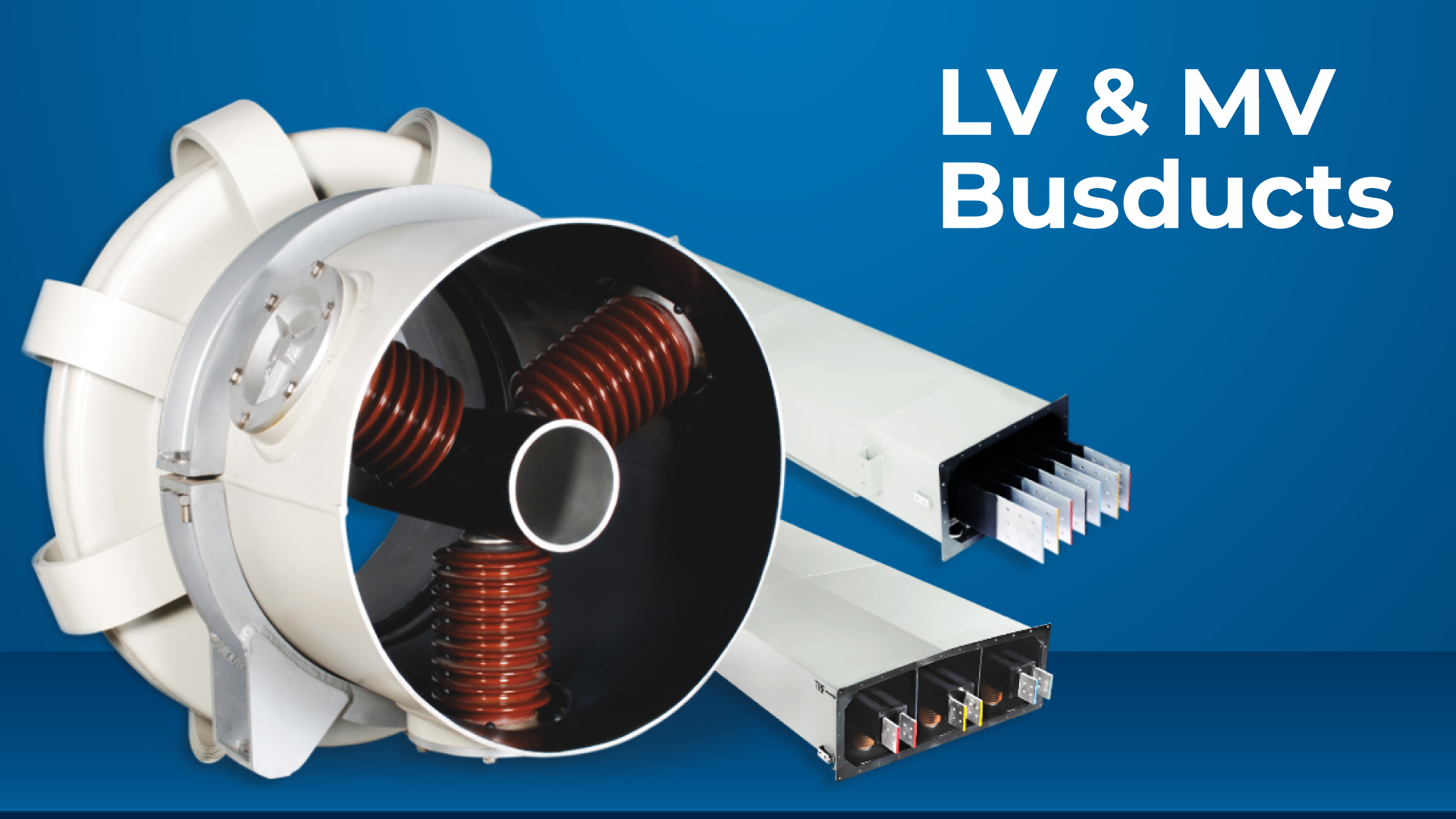
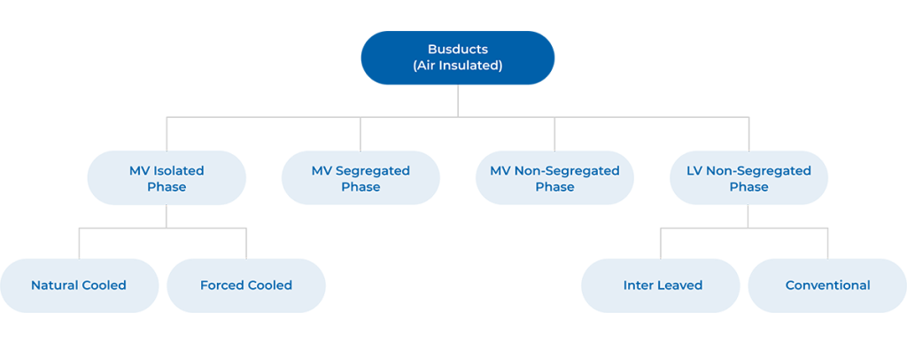
Broadly, the Air Insulated Busducts are classified into Isolated Phase Busduct, Segregated Phase Busduct and Non- Segregated Phase Busduct etc. as depicted in the following sketch and used in Low voltage / Medium voltage applications.
1. MV Isolated Phase Busduct:
Definition:
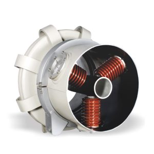
Isolated Phase Busducts, often called Generator Busducts, are commonly used in large power plants to connect generators to transformers and other equipment. Each phase conductor is housed in its own enclosure, which allows it to carry a higher current for a given temperature compared to other types of busducts.
This design eliminates phase-to-phase short circuits and prevents current from being induced in nearby metal structures. The conductors are air-insulated and supported by insulators within the enclosure.
Purpose:
- Isolated Phase Busducts are widely used in power generation units.
- Connection between Generator phase terminals to Generator Circuit Breaker and Generator transformer.
- Tap-off connections to unit auxiliary transformers, station service transformers, excitation transformers and LAVT cubicles.
- Generator neutral formation.
- Delta formation in case of single-phase transformer.
Benefit:
- Excellent shielding under short circuit conditions, near elimination of forces.
- Eliminates phase- to phase faults.
- Reduces proximity effect between the man current carrying conductors of the adjacent phase to almost nil.
- Provides complete protection for operating personnel from touch and high step voltages across the enclosure.
- Suitable for adverse climatic and polluted atmospheric conditions.
- Provides Excellent degree of protection IP65
- The bus system is easy to handle and install.
Range:
| Compliance of standard | IEEE C37.23 / IEC 62271 (1 & 200) / IS 8084 |
| Rated continuous current | 100A – 30,000A |
| Conductor | Aluminum Alloy* |
| Rated Operational Voltage (Ue) | 11 kV – 38 kV |
| Enclosure Material | Aluminum Alloy |
| Rated impulse withstand voltage | 75kV – 170kV (1.2/50µs) |
| Degree of protection | IP55 / IP65 |
*Copper conductor available on request.
2. MV Segregated Phase Busduct:
Definition:
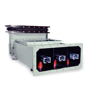
Segregated Phase Busducts (SPBD) are metal-enclosed systems where all phase conductors are housed in a shared enclosure but are separated by barriers. These barriers are either metal barrier (Al Alloy) or insulated barrier (FRP / HGL), The non-magnetic barriers are significantly reduce the forces during phase-to-phase faults.
SPBDs are used in medium-voltage systems for connections between switchgear and transformers.
Purpose:
- Segregated Phase Busducts are widely used in power generating stations, process industries and distribution plants for lower capacity generator connections, inter-connections between switchgear and transformers.
- Connection between generator phase terminals to generator transformer.
- Tap-off connections to unit auxiliary transformers, station service transformers, excitation transformers and LAVT cubicles.
- Connection between transformer to switchgear
- Connection between switchgear to switchgear.
Benefit:
- Better shielding under short circuit conditions by virtue of nonmagnetic metal barrier between phases.
- Reduce proximity effect. Minimizes phase to phase faults.
Range: **
| Compliance of standard | IEEE C37.23 / IEC 62271 (1 & 200) / IS 8084 |
| Rated continuous current | 630A – 5000A |
| Conductor | Aluminum Alloy / Copper |
| Rated Operational Voltage (Ue) | 3.3 kV – 38 kV |
| Enclosure Material | Aluminum Alloy |
| Rated impulse withstand voltage | 40kV – 170kV (1.2/50µs) |
| Degree of protection | IP55 / IP65 |
** Non-Segregated phase busduct (NSPB)-MV Design available on request.
3. LV Non-Segregated Phase Busduct
Definition:
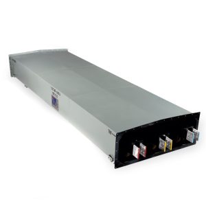
In non-segregated phase busduct (NSPBD), all the three phase conductors are mounted in a common metal enclosure without any metal barriers between adjacent phases.
There are two main types of NSPBDs:
- Conventional Type: Conductors for each phase are placed next to each other, typically in a RYB or RYBN arrangement.
- Interleaved Type: Conductors are arranged in a pattern like RYBN-RYB. This design reduces non-uniform current distribution, lowers and balances impedance, and significantly reduces short-circuit forces. It’s particularly beneficial for long busducts where voltage drop is a concern.
Purpose:
NSPBDs are primarily used for interconnecting switchgear, Power Control Centers (PCC), or Motor Control Centers (MCC) with auxiliary transformers in Power plants / Industrial substations / Petro chemical and steel Industries / Water treatment plants etc.
Benefit:
- It offers low maintenance and easy installation.
- Low voltage drops by virtue of Interleaved design – An important Criterion for Design of LV busducts.
- Suitable for adverse climatic and polluted atmospheric conditions.
- The busduct system is easy to handle and install.
| Compliance of standard | IEC 61439 (1 & 6) / IS 8623 (1 & 2) |
| Rated continuous current | 630A – 6500A |
| Conductor | Aluminum Alloy / Copper |
| Rated Operational Voltage (Ue) | 415V – 1000V |
| Enclosure Material | Aluminum Alloy |
| Rated impulse withstand voltage | 12 kV (1.2/50µs) |
| Degree of protection | IP55 / IP65 |
BUSDUCT ACCESSORIES
Rubber Bellows:
EPDM Rubber Bellows are provided at equipment termination end to prevent transmission of vibrations to busduct and, also to prevent flow of enclosure longitudinal circulating current to the equipment. Rubber bellows also makes it easier to align with equipment flanges and accommodate for equipment/civil foundation tolerances.
Seal-off Bushing:
Seal-off bushings are placed inside the bus duct enclosures near the generator phase side terminal connections to prevent hydrogen from leaking into the bus duct from the generator terminals. Also placed at Indoor to outdoor wall crossing location to prevent the air exchange (in case of non-pressurized IPB). These bushings are made of epoxy cast resin.
Terminations Flexibles:
Copper (or) Aluminium flexibles are provided at all equipment terminals to connect with the bus conductor for easy alignment / assembly with equipment terminals and prevents stress at the joints. Flexibles can be easily fixed or removed without moving the equipment.
Anti-Condensation Heaters:
Thermostatically controlled space heaters are provided at regular intervals in case of SPB and NSPB to avoid condensation in the busduct due to variations in ambient temperature.
Metallic Bellows in Isolated Phase Busduct:
Metallic expansion joints are provided to allow expansion and contraction on conductor and enclosure due to temperature variations. Metallic expansion joints are made of an aluminum alloy, same as that of IPB enclosure, installed in the run of IPB as required by the design calculation. This will also provide a path for the longitudinal enclosure circulating current, which helps achieving a “continuous design” of the IPBD.
AUXILIARY EQUIPMENTS
PT & SP Cubicles:
- PT & SP (Potential Transformers & Surge Protection) cubicles are used for generator voltage measurement and generator protection from over-voltage due to surges.
- A cubicle contains potential transformers, a Surge Arrester, and Surge Capacitors, along with their associated bus bar assembly.
- PTSP Cubicles are designed with an IP-54 Ingress protection and free-standing and floor mounted.
- Potential transformers are mounted on draw-out type carriages and PTs are automatically earthed when the carriage is withdrawn.
- Mechanical interlocking ensures that access to the PTs is only possible after they have been disengaged from the main Busbar system.
Neutral Grounding Cubicles:
- Generator Neutral Grounding Cubicles are designed to minimize fault damage incurred by generators, maintain sufficient fault detection and improve power system reliability.
- This Cubicle housing a neutral grounding transformer and a neutral grounding resistor along with its associated assembly.
- NG Cubicle is free-standing floor mounted type and designed with Ingress protection of IP-54 for the NGT and IP-23 for the NGR compartments.
Pressurization System:
- The pressurization system is used to maintain positive pressure above atmospheric pressure by few millibars of dry, clean air inside the enclosures, in order to prevent any entry of outside air into the busduct thus eliminating any dust or moisture into the busduct.
- It helps in maintaining good dielectric characteristics of the insulator during continuous operation and eliminates condensation.
Hot Air Blowing System:
- The Hot Air Blowing system is required for blowing hot air into the busduct to evacuate moisture content inside the busduct during first time energizing or starting after maintenance
- This system is open loop circuit with hot air supplied through inlet valve until the interior of enclosure is completely dry. The unit is a low voltage equipment comprising axial flow fan, a heater, an inlet filter, pressure damper and can be customized with required controls and interlocks.
Frequently Asked Questions
Busduct is an electrical equipment which serves as interconnection between two or more electrical equipment to transfer the power efficiently and effectively without any disturbance to the system.
Busduct comprises of current carrying part (conductor) which is supported on insulators in a non-magnetic dust tight enclosure, which provides safety to personnel and reduces likelihood of faults.
In early times, it had been a conventional practice to transport power from one equipment to other by means of cables and it did serve the purpose as long as the requirement of power to be transported was quite low. But in fast-changing scenario, the size and capacity of various equipment have increased to a great extent. To transport such large amounts of power, cable was not viable due to its own limitations and inherent disadvantages. To overcome this lacking in power transmission and distribution, we were forced to think of alternatives and led to newer methods for transportation of power, i.e. Busduct Technology, which eliminated innumerable problems faced by use of cables.
- As the capacity of power plants and auxiliary systems has increased hugely, there is a need for very high short circuit withstand ratings of the system and in this regard the fault current withstanding capabilities of busducts are several times higher when compared to cables.
- The current carrying capacity of busbar for a given cross-sectional area is much higher for a given permissible temperature rise since the available area for heat dissipation in case of busbar is much higher than the cables.
- Voltage drop in the busduct system is considerably less due to lower impedance.
- Jointing of busbars is simpler than jointing cables for such large ratings.
- Connection to various equipment like switchgears, transformers & generator by means of busbar are made without stressing the equipment terminals, whereas connection of several numbers of cables to the equipment terminals has always made the system more complicated and sometimes even leads to failure of the equipment terminals.
- Operation and maintenance of busducts are much easier than the cables.
Three Types of Air Insulated Busducts
- MV Isolated Phase Busduct (Natural Cooled and Forced Cooled)
- MV Segregated Phase Busduct
- LV & MV Non-Segregated Phase Busduct
MV IPBD:
- Operational Voltage: 11kV – 38kV (AC)
- Continuous Current Rating: 100A – 30,000A
- Short Circuit Rating: up to 450kA for 1 Sec
MV SPBD & NSPBD:
- Operational Voltage: 3.3 kV – 38kV (AC)
- Current Rating: 630 A – 5000A
- Short Circuit Rating: 50kA for 3 Sec
LV NSPBD:
- Operational Voltage: 415 V to 1000V (AC/DC)
- Current Rating: 630 A – 6500A
- Short Circuit Rating: 100kA for 1 Sec
The busduct is type tested as per the IS 8084 / IEC 61439-1&6 / IEC62271-1&200 / IEEE C-37.23 standards from national and international testing agencies, to ensure the performance and safe operations.
Basic parameters shown below for the preliminary selection busduct:
- Voltage rating and BIL Value
- Continuous current rating
- Short circuit current rating
- Ambient temperature
- Temperature rise limits (for conductor and enclosure)
- Busbar material
Note: Above parameters are the basic only and there are various other parameters influencing the busduct design. For same you need to connect with the C&S Electric Sales team.
IPBD:
- For Generator to transformer connections in all kinds of power plants (Thermal / Hydro / Gas / Combined Cycle / Nuclear / Geothermal etc.)
- Synchronous condenser connections.
SPBD:
Segregated Phase Busducts are widely used in power generating stations, process industries and distribution plants for lower capacity generator connections, inter-connections between switchgear and transformers.
NSPBD:
NSPBDs are primarily used for interconnecting switchgear, Power Control Centers (PCC), Motor Control Centers (MCC) with auxiliary transformers in Power plants / Industrial substations / Petro chemical and steel Industries / Water treatment plants etc.