A busbar trunking system distributes electrical power through solid copper or aluminium bars housed in a protective enclosure, rather than through individually insulated cables. It’s also known as a busway, a busbar distribution system, an electrical busbar system, or a power trunking system. Whichever name you’ve come across, the question is usually the same: what is busbar trunking system, and why choose it over cable? In short, a busbar trunking system installs faster, takes up less space, carries higher fault currents more safely, runs cooler, and is considerably easier to extend as a building’s power needs grow. That combination is why it has become the standard choice for high-rise buildings, data centres and industrial plants.
What Is a Busbar Trunking System?
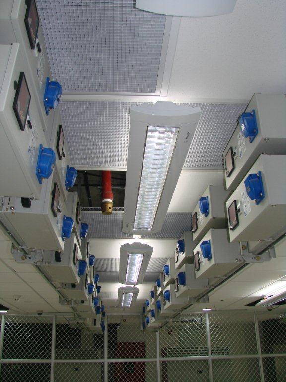
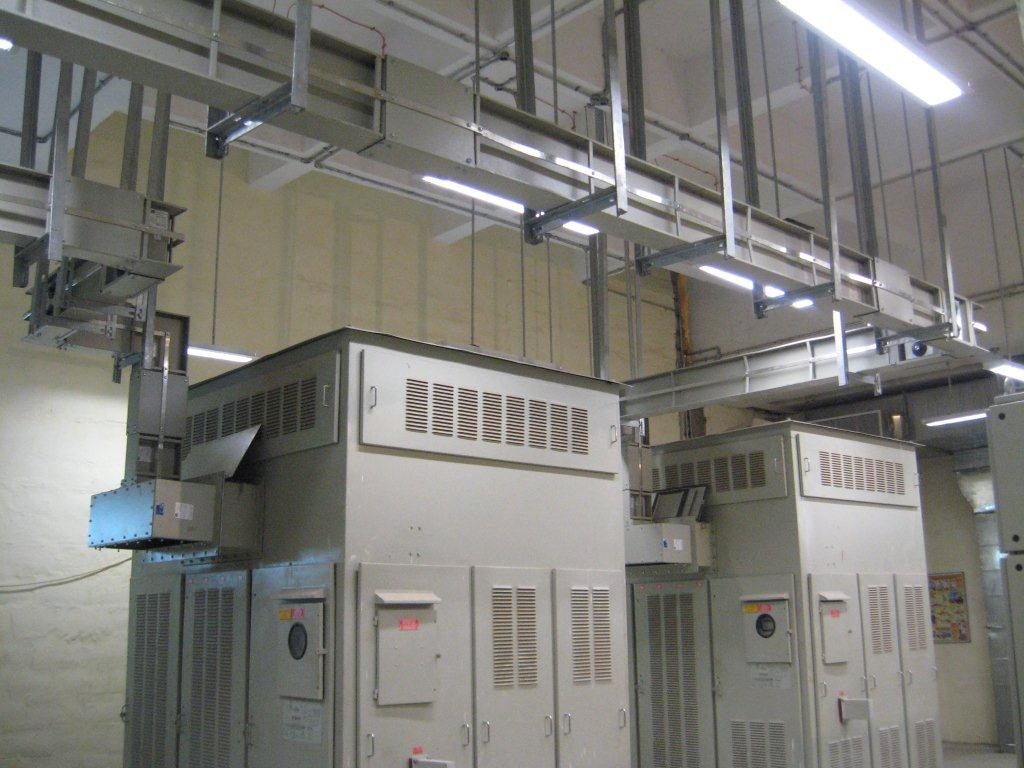
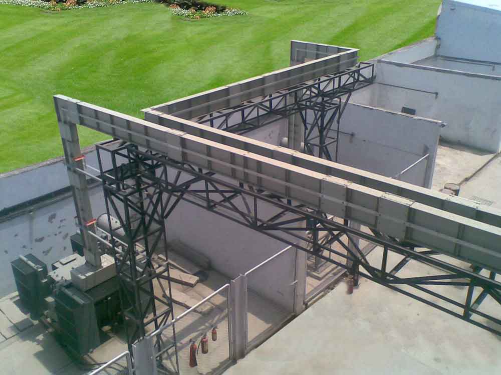
A busbar trunking system is a system of distributing electric power using copper or aluminium busbars with suitable enclosures, engineered to protect the conductors from damage by foreign bodies while giving a defined degree of ingress protection. Busbars are now considered practically irreplaceable in mid-to-large installations because of the convenience and safety they offer over cable. Where traditional cabling requires on-site measuring, cutting and terminating, a busbar trunking system arrives from the factory as a tested, standardised assembly, which keeps both the cost and the installation time considerably lower.
A busbar trunking system is manufactured and type-tested as a complete assembly, typically to IEC 61439-6, the international standard governing the design, testing and performance of busbar trunking systems. That’s a meaningful difference from cable, which is built up and terminated on site rather than certified as a single unit before it reaches the project.
Types of Busbar Trunking Systems
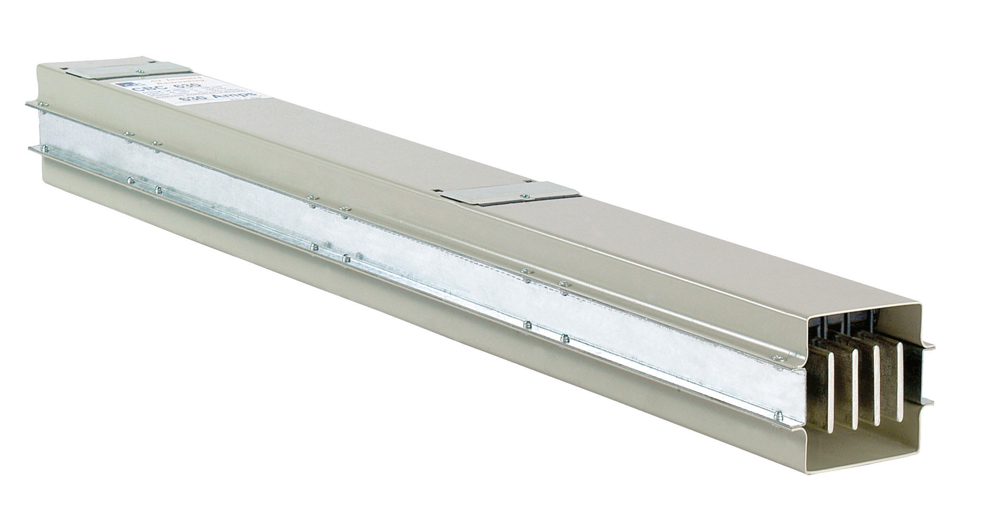
Busbar trunking systems fall into two main constructions. Air-insulated busbar trunking keeps the conductors separated by air within the enclosure. It’s the simpler, more cost-effective option, typically rated up to IP54, and remains common in industrial plants and medium-duty commercial distribution.
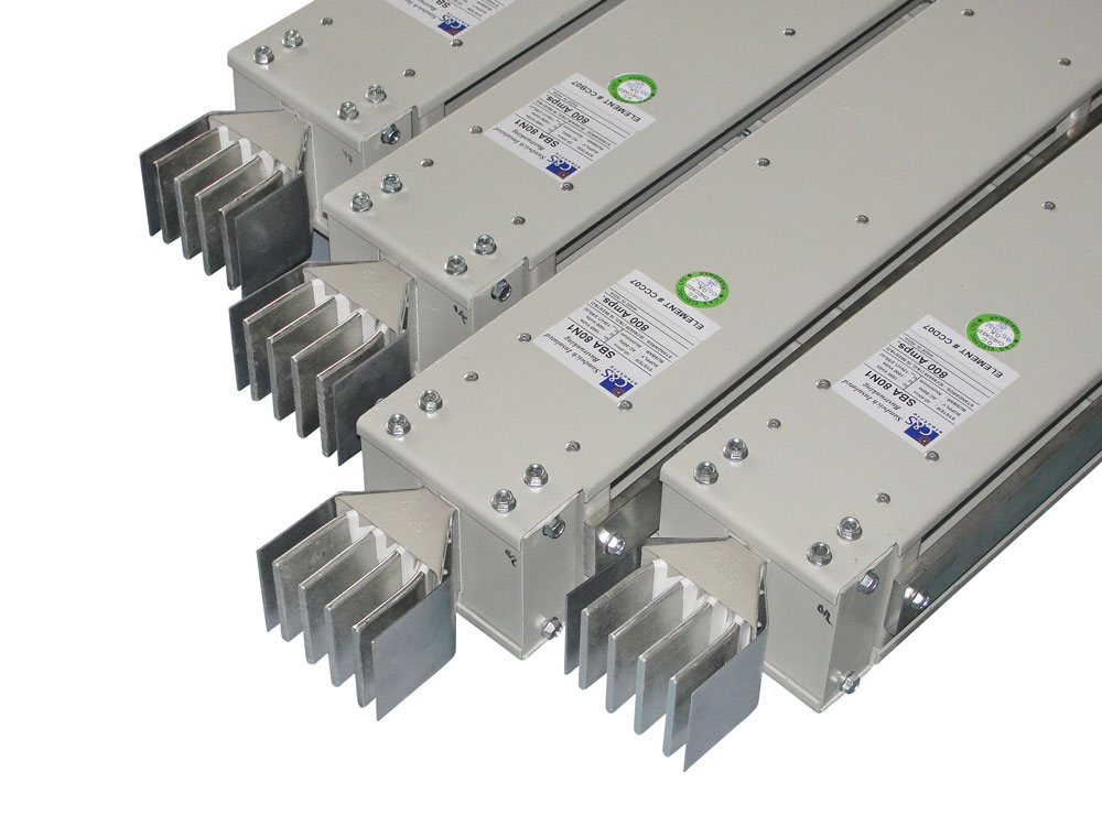
Sandwich, or compact, busbar trunking laminates the conductors tightly together with epoxy or cast-resin insulation and no air gap between them. This reduces reactance and voltage drop, gives a noticeably smaller footprint, and improves fire performance, which is why it’s usually specified for high-rise buildings and data centres. Two further variants build on these constructions: lighting trunking, a lower-current version used for lighting and small power circuits, and rising mains, the vertical form of busbar trunking used to feed each floor through a multi-storey shaft.
Most industrial and commercial projects specify 3 phase busbar trunking, typically in 3-phase/3-wire, 3-phase/4-wire (with neutral) or 3-phase/5-wire (with a separate earth) configurations. C&S Electric’s own range covers this full scope: the Compact Air Busbar Trunking system runs from 125A up to 2000A on copper conductors (IP54, 1000V AC, GI enclosure), and the Sandwich Busbar Trunking system extends up to 7000A on copper conductors, with IP54/55/66 protection options and Zone 5 seismic compliance. The wider range also includes the Lighting Trunking System Metabar and Cast Resin Low Voltage Betobar.
Busbar Trunking vs Cable: What’s the Difference?
Busbar vs cable, or bustrunking vs cable, comes down to a straightforward trade-off: a rigid, factory-tested, modular power distribution system against a flexible conductor that’s assembled and terminated on site. It’s also the most direct answer to why busbar is used instead of wire at higher current ratings: a busbar trunking system carries more current in less space, loses less voltage over a run, and can be extended later through tap-off points, without pulling an entirely new cable.
Busbar Trunking Vs. Cables
Parameter |
Busbar Trunking System |
Conventional Cable |
|---|---|---|
| Installation | Delivered as tested, prefabricated straight lengths, elbows and tap-off units, joined on site with bolted connections. | Cut, pulled and terminated conductor by conductor, run by run. |
| Current rating | Up to 2000A (Compact Air) and up to 7000A (Sandwich) in C&S’s own range | Above a few hundred amps, multiple cables are usually run in parallel to reach the same rating |
| Ingress protection | IP54 as standard, up to IP66 for sandwich systems | Depends on cable type and containment; not tested as a complete assembly |
| Voltage drop | Low, due to close conductor spacing and reduced reactance, particularly with sandwich construction | Higher, and rises further when cables are grouped or derated for ambient temperature |
| Adding new loads | New tap-off units can be fitted at existing tap-off points without a new cable run | Usually requires an entirely new cable to be pulled from the distribution board |
| Short-circuit withstand | Rated and published for the tested assembly, including seismic compliance up to Zone 5 for C&S’s Sandwich range | Depends on cable size and installation method; not verified as a complete assembly |
| Fire behaviour | Sandwich types are epoxy or cast-resin insulated and largely fire-retardant, with no PVC or XLPE jacket to burn | PVC and XLPE insulation can propagate fire and release smoke |
| Maintenance | Joints are visible, bolted, and easy to inspect or thermally scan | Faults are hidden inside conduit or trunking and can be harder to trace |
| Features | Finishing is very good, hence adds to aesthetics of building | Improper laying of the cables may spoils the aesthetics of building |
| Multiple floor building power feeding can be done with single Bustrunking system | Multiple floor building power feeding has to be done with multiple cable sets. This make the complete system cumbersome. | |
| Power tap off can be done from the single system installed. In case the load changes we have to just replace the Tap off boxes of higher rating. | Not possible. Additional cables to be laid till the particular floor. | |
| Structure | Example for 3200A(Cu) dimensions: 151(w)x340(h) and light in weight. | Cables and its structure 700mm wide i.e., cable tray etc. is very heavy and occupies more space. |
| Total run is made up of multiple elements which are joint together. Thus making the complete system maintenance friendly. | A single length of multiple cables is installed, making maintenance nonfriendly. | |
| Easy retrofitting of the element is possible in case the location and consumer load change. | Easy retrofitting of the element is not possible in case the location and consumer load change. | |
| Totally enclosed, cannot be tampered. Fit and forget system. | Insulation can wear off with time. Can get damaged by rodents. Has to maintained on regular basis. | |
| Termination | Direct termination through busbars | The method for cable termination is very cumbersome. |
| The termination is simple and easy. | Additional supports are required to hold the cables inside the panel. | |
| Have a highly compact structure and can be bent up to 90 degrees. | Cables are generally installed in bundles & with such a cross section that they cannot be bent tightly. | |
| Time & cost consumption | When sizing busbars, the designer only needs to make calculations on a single riser which reduces design time and costs. | It is necessary to protect each cable individually with a fuse and when laying the cables in bundles it is necessary to anchor them properly so that they can withstand the electrodynamic forces generated in the event of a short ckt. So, the designers have to spend more time on calculations. |
| Use of additional items | No additional support is required. | Heavy labor is required to lay the cables. |
| No extra holes/cutouts are required. | Holes to be made in the gland plate for fixing cable glands. | |
| No cable tray is required, supported on ceiling / wall. | Cable tray or the digging of the trench is required to lay the cables. | |
| No special tools are required. | Special tool are required for crimping the cable lugs. | |
| Design verified switchgear assembly, limits from manufacturer’s catalogue. | Limits depend on the laying method and cable accumulation. The derating factor must be determined / calculated. | |
| Halogen Free | Principally free from halogen. | PVC cables are not free from halogen. Halogen-free cables are very expensive. |
| Damage by rodents | Busbar systems cannot be damaged by various rodents, which prevents the steel casing. | Cables can be damaged by various rodents. |
Both busbar trunking and cable are subject to the same statutory voltage-drop limits (3% for lighting circuits, 5% for other circuits, measured from the origin of the installation, per BS 7671 / IEC 60364). Exact current ratings, IP classes and short-circuit figures vary by product; always confirm against the specific datasheet before finalising a design.
Advantages of a Busbar Trunking System Over Conventional Cable Distribution
Compact Design and Space Saving
Busbars have a compact design that lets compressed, flat conductors run through a much smaller enclosure than an equivalent cable installation would need. That’s a genuine advantage wherever thousands of amperes must be transmitted through a limited service riser or plant room.
Better Heat Dissipation
The compact design and metal casing, combined with a well-defined conductor surface, let a busbar trunking system absorb and dissipate heat more effectively than insulated cable, so connected equipment tends to run cooler.
Flexibility for Future Expansion
Busbars are considerably more flexible than cable in practice. They can be configured to suit almost any building layout, modified easily if a room or floor is added later, and relocated without major capital expense.
Faster Installation and Lower Installed Cost
Busbar sections mount more quickly than cable and cost less to install, largely because the product arrives from the factory as a tested, standardised assembly rather than being built up on site. That also makes costs easier to estimate accurately at the design stage, since the technical characteristics and price of each component are already known.
Better Resistance to Short Circuits
The rigid construction of a busbar trunking system gives it better resistance to short-circuit faults than cable. The conductors are held at a fixed, minimum distance from each other, which reduces induced resistance, and the flat, thin profile helps distribute current density evenly across the bar.
Improved Safety and a Cleaner Installation
Sandwich busbar systems are epoxy or cast-resin insulated and largely fire-retardant, with no air gap for fire to spread through and no PVC or XLPE jacket to produce toxic smoke if it does. Busbar trunking also keeps plant rooms and risers visibly tidier, without the tangle of cable trays and conduit that conventional wiring tends to accumulate over time.
Lower Total Cost of Ownership
Comparing busbar against cable on material cost alone misses most of the picture. At higher current ratings, cable needs multiple parallel runs, supporting trays and considerably more installation labour, and tracing a fault inside a cable run takes longer than inspecting a bolted busbar joint. Once installation time, maintenance and expected service life are factored in, a busbar trunking system is typically the cheaper option over the life of the installation.
Where Busbar Trunking Systems Are Used
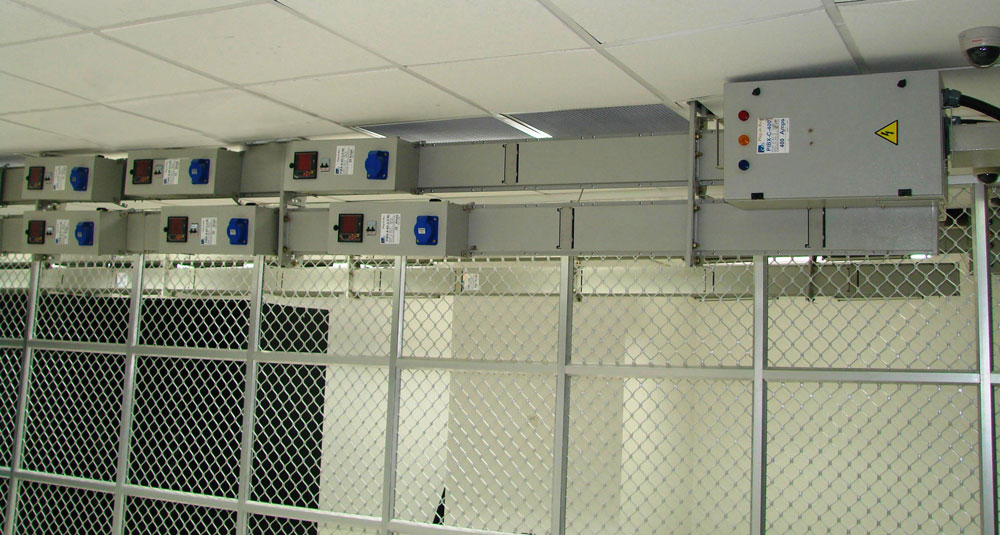
Busbar trunking systems are specified wherever large amounts of power need to be distributed compactly and reliably, including:
- High-rise buildings and rising mains, where vertical shaft space is limited
- Data centres, where low voltage drop and high reliability are essential
- Manufacturing and industrial plants, feeding heavy machinery and switchgear
- Commercial complexes and IT parks that need clean, modular power distribution
- Hospitals and other critical-power facilities, where fault resistance and reliability matter most
Busbar Trunking System Installation: What to Expect
A busbar trunking system installation generally follows the same sequence regardless of building type. Load calculation and route planning come first: working out current rating, diversity factor, route length and ambient conditions before a system size is chosen. The straight lengths, elbows, tees and tap-off units are then assembled to match the project layout, and the run is supported on hangers or brackets at the intervals the manufacturer specifies.
Every bolted joint needs to be tightened to the correct torque; under- or over-tightening a joint is one of the most common causes of in-service faults, so this step is worth getting right. The enclosure is earthed continuously along the full run, and before the system is energised, insulation resistance, continuity and, where appropriate, thermal imaging checks are carried out as part of testing and commissioning. After that, routine inspection should continue at least once a year, and more often in high-load environments, checking joints, grounding and enclosure condition.
Why Choose C&S Electric
C&S Electric has been engineering electrical distribution equipment in India since 1966 and is one of the country’s leading manufacturers of busbar trunking systems. The range covers the Compact Air Busbar Trunking system, the Sandwich Busbar Trunking system, the Lighting Trunking System Metabar, and Cast Resin Low Voltage Betobar, spanning everything from small lighting circuits to heavy industrial and high-rise power distribution. Get in touch with our team to find the right busbar trunking system for your project.



FAQs
It’s a factory-assembled system for distributing electrical power using solid copper or aluminium busbars inside a protective enclosure, used instead of insulated cable. You’ll also see it called a busway, a busbar distribution system, or a power trunking system.
Because it installs faster, carries more current in less space, loses less voltage over a run, withstands short-circuit faults better, and can be extended later through tap-off points rather than requiring a new cable to be pulled.
Busbar trunking is a rigid, factory-tested, modular assembly with bolted joints and tap-off points. Cable is a flexible, insulated conductor that’s installed and terminated on site. Busbar trunking generally installs faster and holds a lower voltage drop; cable is often more economical for small, point-to-point loads.
The two main constructions are air-insulated, where the conductors are separated by air, and sandwich (or compact), where the conductors are laminated together with epoxy or cast-resin insulation for a smaller footprint and lower impedance. Lighting trunking and rising mains are application-specific variants of the same technology.
Yes. Most industrial and commercial busbar trunking systems are supplied as 3-phase, in 3-phase/3-wire, 3-phase/4-wire or 3-phase/5-wire configurations.
It’s another name for a busbar trunking system: a modular, enclosed system of copper or aluminium busbars used to distribute power in place of cable.
That depends on the type and conductor material. C&S Electric’s Compact Air Busbar Trunking system covers 125A to 2000A, and the Sandwich Busbar Trunking system extends up to 7000A. Always check the specific product datasheet for exact ratings.